Industrial practice · Synthetic case-study library
Think like a commissioning engineer.
Work through credible field evidence, challenge assumptions, reject unsafe shortcuts and prepare a professional handover. These cases are ungraded training companions, not proof of certification or authorization.
Separate observations from assumptions, estimates and unverified reports.
Identify what remains unknown and what evidence would discriminate between possible causes.
Record process limits, independent safeguards, required permissions and mandatory stop conditions.
Select a proposed simulated next step, then compare it with the engineering reasoning.
Prepare an evidence-backed turnover: trends, revisions, constraints, unanswered questions and review owner.
Case 1 · Data center cooling · Intermediate · 35–45 minutes
Unstable cooling-water flow during load changes
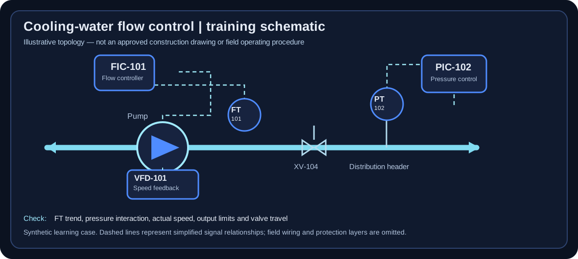
Original illustrative schematic, not a plant P&ID, wiring diagram, control narrative or approved construction document. Use the data and assumptions in this case rather than inferring undocumented field connections.
A variable-speed pump delivers cooling water to a heat-rejection system. The flow trend oscillates after a staged load increase, and operators have proposed raising PID gain.
This is a synthetic training skid. Flow is measured in m³/h; the controller commands a VFD speed reference in percent. The real system would require a site-approved test plan and thermal-risk review.
Available evidence
Flow SP = 115 m³/h; measured PV swings between 105 and 124 m³/h in a roughly 34-second cycle.
The controller output cycles between 48% and 71%, but actual pump-speed feedback is delayed by approximately 4 seconds.
The downstream distribution valve reaches its travel limit during peak demand.
A secondary pressure controller is active, but its interaction with flow control is not yet characterized.
Questions still open
Whether the oscillation starts in the flow loop, pressure loop, or upstream supply.
Whether the pump is experiencing a minimum-flow or cavitation risk at the operating point.
Whether actuator constraints and sensor filtering have been correctly modeled.
Your investigation plan
Write your own sequence before checking the suggested approach.
Reveal the recommended investigation steps
Mark flow SP, PV, CO, pump speed feedback and valve position on a common timebase; verify instrument units and sample timestamps.
Identify limits, selectors, anti-windup behavior, active control mode and protection-system constraints.
Examine phase relationships with pressure and demand trends; formulate at least two competing hypotheses.
Specify a supervised simulation-only comparison with unchanged disturbances, candidate conservative tuning and a constrained operating envelope.
Decision challenge
Choose a defensible response mentally, then reveal its rationale. These choices do not alter stored learner scores.
A. Increase gain immediately because PV is oscillating
Not recommended. Gain changes without identifying the root cause can amplify interaction and output cycling.
B. Hold tuning changes, check active limits and interactions, then compare synthetic alternatives
Preferred judgment. This preserves system constraints and recognizes that a limit or adjacent controller may be driving the apparent instability.
C. Disable the downstream valve limit to simplify the experiment
Not recommended. Equipment limits and protective constraints must not be bypassed to obtain cleaner training data.
Reviewer acceptance rubric
Distinguishes observed facts from hypotheses and explicitly lists the limited evidence.
Identifies at least one mechanical/actuator hypothesis and one multi-loop interaction hypothesis.
Proposes reproducible comparison criteria: flow deviation, CO travel, saturation duration and recovery under the same disturbance.
Escalates any protective-limit, thermal or hydraulic concern before proposing a field test.
Turnover package checklist
Trend evidence with units and times
Control structure and protection-boundary sketch
Alternative diagnoses and next safe tests
Review approval and unresolved questions
Safety boundary: No production pump-speed changes, valve-limit changes, or control-mode changes are authorized by this synthetic case.
Case 2 · Chemical processing · Advanced · 40–55 minutes
Reactor temperature lag and cascade-loop uncertainty
A simulated jacketed batch reactor experiences delayed temperature recovery after feed-temperature disturbances. A proposed cascade design would use jacket supply temperature as a faster secondary variable.
This educational process is not an exothermic-reaction safety study. It contains a synthetic temperature controller and an inner jacket-temperature loop; independent high-high temperature protection must remain outside the control tuning exercise.
Available evidence
Primary process temperature has an apparent 75-second lag and approximately 22-second effective delay in a controlled test.
Jacket supply temperature responds in approximately 12 seconds in a separate synthetic observation.
The secondary temperature transmitter occasionally reports implausible spikes; quality flags are available.
The steam valve has a minimum opening and can saturate at high heat demand.
Questions still open
Whether the inner-loop actuator and transmitter remain reliable over the batch operating range.
Whether the apparent delay changes as jacket circulation and feed conditions vary.
Whether the proposed cascade fallback will track outputs bumplessly after a bad secondary sensor reading.
Your investigation plan
Write your own sequence before checking the suggested approach.
Reveal the recommended investigation steps
Draw the primary/secondary measurement paths and specify which controller writes the secondary setpoint.
Compare inner-loop versus outer-loop timescales without assuming a single operating-point estimate is universal.
Define bad-PV quality, saturation, tracking and fallback test cases before trying a synthetic cascade structure.
Use identical disturbance sequences to compare baseline control with the candidate cascade and record constraints and uncertainty.
Decision challenge
Choose a defensible response mentally, then reveal its rationale. These choices do not alter stored learner scores.
A. Deploy cascade because 12 seconds is less than 75 seconds
Not recommended. Relative speed is necessary but insufficient; sensor validity, saturation, tracking and process safety must also pass.
B. Ignore the secondary transmitter spikes because the primary loop filters them
Not recommended. A bad inner-loop measurement may propagate into actuator commands and disrupt temperature control.
C. Study cascade with explicit invalid-sensor, saturation and bumpless-transfer acceptance cases
Preferred judgment. A reliable inner loop can improve disturbance rejection, but its failed-measurement and tracking behavior must be verified.
Reviewer acceptance rubric
Explains cascade causality and why the proposed secondary loop might improve rejection of jacket-side disturbances.
States realistic failure modes for sensor spikes, actuator saturation, tracking and batch transition.
Does not confuse process control with an independent protective system or claim a synthetic controller establishes reactor safety.
Includes measurable acceptance criteria and an escalation/approval point.
Turnover package checklist
Control architecture diagram and operating assumptions
Nominal and stressed simulated trends
Failure and fallback matrix
Required independent process-safety reviews
Safety boundary: Reactor or combustion-control designs demand site process-hazard review and qualified approval; training neither substitutes for protection systems nor authorizes field changes.
Case 3 · Water and wastewater · Intermediate · 35–45 minutes
Level-control troubleshooting before pump station turnover
A simulated wet-well level loop repeatedly overshoots despite a recent tuning change. Maintenance suspects the level transmitter; operations suspect pump minimum-speed constraints.
A synthetic wastewater pump station uses level feedback and variable-speed pumping. Redundant high-high level alarm, environmental discharge requirements and lockout procedures are outside any learner authority.
Available evidence
Level SP = 3.2 m; PV approaches 3.8 m during a simulated inflow surge.
CO demand reaches 92%, while simulated pump feedback stops increasing near 76% of rated speed.
The level trend has occasional 0.12 m upward spikes unrelated to measured inflow.
An operator reports that an anti-windup or tracking configuration was recently modified, but no change record is available.
Questions still open
Whether speed is constrained by the drive, hydraulic operating point or a separate protective limit.
Whether level spikes are instrument noise, foam, electrical interference or real inflow pulses.
Whether integral accumulation occurred during saturation.
Your investigation plan
Write your own sequence before checking the suggested approach.
Reveal the recommended investigation steps
Collect time-aligned inflow, PV, SP, CO, actual pump speed, alarm flags and minimum/maximum limits.
Identify the last approved configuration and compare tracking/anti-windup settings against a controlled baseline.
Separate sensor spikes from physical process response with independent evidence.
Prepare a restoration and turnover package naming unresolved faults and who must approve further work.
Decision challenge
Choose a defensible response mentally, then reveal its rationale. These choices do not alter stored learner scores.
A. Disable the high-high alarm to obtain a clean tuning response
Not recommended. Alarms and protective functions cannot be disabled to make a training or plant test more convenient.
B. Investigate saturation and anti-windup tracking before another tuning change
Preferred judgment. A limited actuator and integral accumulation can create overshoot that gain changes alone do not cure.
C. Assume every level spike is a real hydraulic event
Not recommended. Corroborating the measurement with other evidence is necessary before diagnosing a physical surge.
Reviewer acceptance rubric
Separates controller command from actual pump response and recognizes possible saturation.
Explains integrator windup qualitatively and why tracking/anti-windup evidence matters.
Identifies independent level verification and alarm/protection boundaries.
Produces a clear unresolved-items list for maintenance and operations.
Turnover package checklist
Revision-controlled configuration baseline
Evidence of actuator limits and tracking
Instrument cross-check record
Punch-list owner, priority and handover acceptance
Safety boundary: The case is a synthetic lesson. Never bypass flood protection or environmental alarms or modify pump controls without site authorization.